

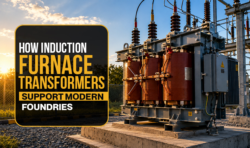
Walk through a modern foundry, and you'll hear a lot about the furnace itself: its capacity, its melt rate, the grade of metal coming out. What you won't hear much about is the transformer sitting in the adjacent electrical room, quietly making all of it possible. The induction furnace transformer is one of the least glamorous pieces of equipment on site, yet it's the component that every other part of the process depends on.
The global induction furnace market stood at USD 1.5 billion in 2025 and is expected to reach USD 2.3 billion by 2032, growing at a CAGR of 6.1% That growth is coming from foundries upgrading their melting infrastructure, and a good chunk of that upgrade spend goes into the power supply chain, including the transformer. Getting this piece right has a direct impact on what comes out of the furnace.
So, how exactly does a foundry transformer support the operation? The answer is more specific than most foundry managers realise.
What an Induction Furnace Transformer Actually Does
An induction furnace doesn't work on a direct AC connection. The process requires DC power, or at a minimum, a tightly controlled variable-frequency AC supply, depending on the furnace design. The transformer's job is to step down the incoming grid voltage, typically 11 kV or 33 kV, to the lower voltage level that the rectifier or inverter needs to work with.
From there, the rectifier converts AC to DC, and the inverter generates the high-frequency current that flows through the induction coil. That coil creates an electromagnetic field, and that field is what actually heats and melts the metal.
What this means in practice: the transformer's output quality directly affects how the rectifier and inverter perform. Voltage instability, harmonic content, or poor regulation at the transformer stage doesn't stay at the transformer stage. It propagates through the entire power chain and shows up as inconsistencies in the melt.
Voltage Regulation and Melt Quality
Temperature control is central to producing consistent castings. For iron foundries casting engine components or pump housings, even a 20-30°C deviation in tapping temperature can mean the difference between a sound casting and a reject.
The induction furnace transformer supports temperature control in two ways. First, it allows the furnace operator to vary power input by changing the transformer tap position, which adjusts the secondary voltage and, consequently, the power delivered to the coil. Second, a transformer with tight voltage regulation ensures that variations in the grid don't propagate into the furnace.
Modern foundry transformer designs often include on-load tap changers (OLTCs) that allow power adjustment without taking the furnace offline. In high-volume foundries running multiple heats per shift, this flexibility has a measurable impact on productivity.
Handling Harmonic Disturbances
Induction furnace power systems generate harmonics, particularly the 5th and 7th orders. These feed back into the transformer and, if not managed, into the wider plant electrical system. A transformer not designed for this environment will run hotter than expected, age faster, and require more frequent maintenance.
Foundry transformer specifications for induction applications typically call for:
- Delta-delta or delta-star winding configurations that cancel specific harmonic orders
- Heavier conductor cross-sections to handle the additional current from harmonic content
- Enhanced cooling capacity, because harmonic losses convert into heat inside the transformer
ABB announced in February 2025 the launch of packaged rectifier systems with integrated IGBT/thyristor technology for induction furnace power supplies, a development that places greater demands on the upstream transformer to deliver clean, stable input.
Energy Efficiency: Where the Transformer's Role Becomes Financial
Energy is typically the highest operating cost in a foundry. The induction furnace transformer contributes to energy performance in two ways: its own no-load and load losses, and its effect on power factor.
A transformer with high core losses wastes energy continuously, even during idle periods between heats. In a foundry running 20+ hours a day, those losses add up. Modern amorphous core designs and high-grade silicon steel laminations reduce no-load losses significantly compared to older transformer stock.
Power factor correction is the other side. Induction furnaces are inherently inductive loads, which means poor power factor without compensation. Some modern foundry transformer configurations incorporate capacitor banks or active compensation into the transformer installation, reducing reactive power demand and the associated utility penalties.
Reliability and Planned Maintenance
An unplanned transformer outage in a foundry doesn't just stop the furnace. It freezes the metal in the crucible, which can damage the lining and require a full rebuild before the next heat. The downstream cost of a transformer failure can be ten to fifteen times the cost of the transformer itself.
This is why foundries increasingly specify transformers with built-in monitoring: winding temperature sensors, oil level indicators, and dissolved gas analysis (DGA) ports. Early warning of developing faults allows maintenance teams to plan interventions during scheduled downtime rather than responding to emergencies.
For foundries modernising their melting operations, the induction furnace transformer deserves the same engineering attention as the furnace itself. Makpower Trans-Systems designs and supplies transformers specifically for induction furnace applications, including the harmonic handling, tap changing, and cooling specifications that foundry operations actually require.
Related Posts

Dry Type vs. Oil Type Transformers:What You Need to Know
Transformers are getting more popular for modifying the supply.....
What is Transformer Oil & Its Importance
Transformer oil, also known as insulating oil, has a crucial.....

What are The Main Functions of a Transformer?
Transformers play a significant role in efficient electrical energy.....

Why Transformers Are Essential to the Industrial Sector?
Sufficient power supply is the backbone of any industrial operations.....