
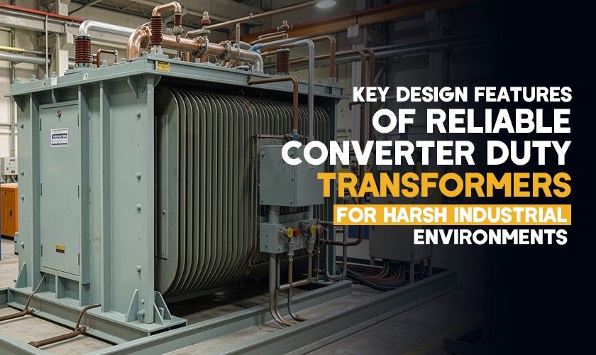
The steel plant in Jharkhand experienced a loss of three standard transformers during eleven months. The reason? They were using a transformer that wasn’t designed for the load profile. Procurement inertia prevented progress from being made.
The replacement transformer, which meets proper specifications as a converter duty transformer , has operated continuously for more than four years without experiencing any unexpected shutdowns.
The global transformer rectifier market is valued at USD 1.94 billion in 2025, which will increase to USD 2.66 billion by 2032. That growth reflects industries finally accounting for their real electrical environment.
The main distinction between a converter duty transformer and a standard unit lies in their design differences. The majority of the process occurs within the winding components.
Harmonics Aren’t a Nuisance: They’re a Design Parameter
The 6-pulse rectifier circuit produces harmonic currents at 5th, 7th, 11th, and 13th frequencies. This concept exists as a fundamental principle of physics. The 12-pulse system decreases some harmonics but fails to remove all of them. The harmonics create extra copper losses, which depend on the operating frequency. The system generates heat because of magnetic fields that escape from the core. The system creates unwanted magnetic fields, which increase the temperature of components that lack a heat sink design.
A properly constructed converter duty transformer uses continuously transposed conductors (CTC) as the main component for its larger systems. The system achieves better loss distribution because eddy current losses spread throughout the entire winding system. The core uses thinner laminations, which consist of 0.23 mm grain-oriented steel, while standard power transformers use 0.27 to 0.30 mm laminations.
The system decreases iron losses, which occur at high-frequency operations. The most common design error I encountered in my work was designing the neutral conductor system with insufficient capacity. The neutral wire must handle 1.5 to 1.7 times the current of each phase during triplen harmonics. The two available solutions require either designing for the system or replacing the cable tray after a fire incident.
Thermal Management Beyond the Nameplate
The nameplate kVA rating of a converter duty transformer creates misleading information about its actual capacity. The 2,000 kVA system, which feeds a rectifier stack, operates at higher temperatures than the system which feeds lighting loads with the same power consumption.
A poorly compacted soil area close to a riverine zone will show differential settlement after two monsoon periods. Uneven settling stresses bushing connections and can misalign radiator banks.
India increased its transformation capacity by 86,433 MVA during FY2024-25, which marks a 22.2% annual growth. The majority of this capacity supports industrial substations that require converter loads as their primary power source. The thermal design needs K-factor ratings. A K-13 rated transformer handles a typical 6-pulse VFD. The K-1 rated unit, which represents standard transformers, remains completely ineffectual.
Large converter duty systems require their oil distribution system to direct oil flow through the hottest winding segments. The practice of depending on natural convection within a 3000 kVA rectifier system represents gross negligence.
Insulation That Takes a Beating
The commutation process in converter circuits generates voltage spikes. The winding insulation experiences a transient every time a thyristor or IGBT undergoes switching. The system accumulates this continuous operation, which extends beyond 1000 cycles each second.
The insulation system employs inter-turn barriers that have increased thickness, together with pressboard spacers of superior quality and additional crepe paper covering for its high-voltage winding insulation. The problem extends beyond thickness, as the actual problem exists. The partial discharge inception voltage (PDIV) represents the actual problem.
Micro-discharges develop from repetitive voltage spikes, which gradually damage insulation materials throughout their operational voltage range. Better manufacturing companies conduct PDIV testing at their factories under simulated harmonic conditions. The requirement for testing exists in IS 2026. The requirement should be implemented.
Conclusion
A converter duty transformer functions as an engineering solution which requires dedicated design work because standard transformers lack the capacity to meet specific application needs. The cost premium ranges between 15 and 25 per cent.
The total expenses from three early breakdowns that occurred within eleven months, which included production halts and urgent material purchases,, exceed the costs of three early breakdowns.
You can find dedicated converter duty solutions at Makpowerts. It should be defined according to the actual operational requirements rather than the equipment's rated capacity. The entire educational content exists within that single statement.
Stats Used:
1. 1. Transformer rectifier market USD 1.94B in 2025, projected USD 2.66B by 2032, CAGR 4.6% | Coherent Market Insights
2. 86,433 MVA capacity added in FY2024-25, 22.2% increase | TNDIndia / CEA
Related Posts

Dry Type vs. Oil Type Transformers:What You Need to Know
Transformers are getting more popular for modifying the supply.....
What is Transformer Oil & Its Importance
Transformer oil, also known as insulating oil, has a crucial.....

What are The Main Functions of a Transformer?
Transformers play a significant role in efficient electrical energy.....

Why Transformers Are Essential to the Industrial Sector?
Sufficient power supply is the backbone of any industrial operations.....