

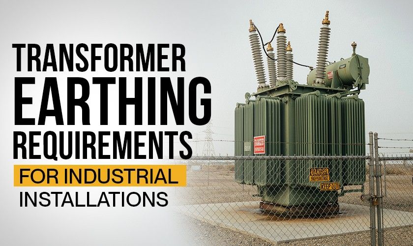
A transformer's performance isn't only about its electrical design. How well it's earthed matters just as much, for the people working near it, the equipment it feeds, and how it holds up when something goes wrong electrically.
Transformer earthing gives fault current a low-impedance path into the ground, which is what lets circuit breakers and relays actually do their job. Skip proper grounding, and fault current can linger longer than it should, raising the odds of equipment damage, fire, or shock.
In industrial facilities where a transformer is feeding critical production equipment, the grounding system isn't a side detail. It's part of the core electrical infrastructure.
Why Transformer Earthing Is Critical
Transformer earthing, also called transformer grounding, does more than satisfy a design standard on paper. A properly designed system helps:
- Protect personnel from dangerous touch and step voltages
- Improve the operation of protective relays and circuit breakers
- Reduce equipment damage during insulation failures
- Stabilize system voltage with respect to earth
- Improve overall power system reliability
Industrial transformers face faults from insulation breakdown, cable failures, switching operations, moisture ingress, and lightning. A well-designed earthing system limits the fallout from all of these by giving fault current somewhere safe to go.
Key Components of a Transformer Grounding System
An industrial transformer grounding system is really several components working together as one protective network.
Earth Electrodes
Earth electrodes are the physical link between the installation and the surrounding soil. Depending on the site, they may include:
- Ground rods
- Earth plates
- Ground grids
- Ring earth systems
Which one you use comes down to soil resistivity, expected fault current, available space, and the applicable design standard.
Earthing Conductors
Earthing conductors tie the transformer tank, neutral point, and associated equipment into the grounding network. They need enough mechanical strength and current-carrying capacity to survive the maximum fault current without damage.
The Central Electricity Authority (CEA) calls for dedicated earthing terminals on transformer tanks. For power transformers specifically, two earthing pads at diagonally opposite bottom corners are recommended for secure grounding connections.
Neutral Grounding
The transformer neutral is often grounded to give the electrical system a reference point and improve fault protection. Depending on the application, this may take the form of:
- Solid grounding
- Resistance grounding
- Reactance grounding
- Grounding through a neutral grounding resistor (NGR)
IEC 60076-25:2023 sets out the requirements for neutral grounding resistors used to limit earth fault current while keeping protection performance intact.
Bonding of Metallic Components
Transformer tanks, radiators, marshalling boxes, cable glands, support structures, and other exposed metal parts all need bonding into the earthing system. Bonding keeps every conductive component at roughly the same electrical potential during a fault, which is what actually cuts the shock risk.
Best Practices for Transformer Earthing
A grounding system is only as good as its design, installation, and upkeep.
Maintain Low Earth Resistance
Lower earth resistance means faster fault current dissipation and quicker clearing by protective devices. There's no single target figure here. The right resistance depends on system design, fault current calculations, soil characteristics, and the applicable standard.
Use Properly Sized Earthing Conductors
Size grounding conductors around prospective fault current, thermal withstand capability, and mechanical durability. Undersized conductors can overheat or fail exactly when you need them most.
Protect Against Corrosion
Industrial sites expose grounding systems to moisture, chemicals, and corrosive soil. Corrosion-resistant materials and regular inspection are what keep the system reliable over years, not just at commissioning.
Ensure Secure Mechanical Connections
A loose or damaged connection quietly raises resistance and weakens the whole system. Mechanical joints need periodic inspection for corrosion, looseness, or physical damage.
Integrate Earthing With Overall Plant Protection
Don't treat transformer grounding as its own isolated system. Coordinate it with:
- Plant grounding grid
- Lightning protection system
- Switchgear grounding
- Cable shielding
- Protective relays
An integrated design clears faults faster and keeps the whole system more stable.
Common Transformer Earthing Mistakes
When conducting the transformer earthing, the following mistakes are often made:
- Poor soil assessment. Skip the soil resistivity survey, and you may end up with higher-than-expected earth resistance and weaker fault current dissipation.
- Inadequate bonding. Cable trays, structural steel, or auxiliary equipment left disconnected from the grounding network create potential differences during a fault.
- Damaged or corroded conductors. Mechanical damage and corrosion raise resistance over time. Regular inspection catches this before it affects performance.
- Lack of periodic testing. Grounding systems shift over time with soil conditions, seasonal moisture, corrosion, and mechanical wear. Periodic testing is the only way to confirm the system still performs as designed.
Transformer Earthing Inspection Checklist
During the installation process, be sure to go through the transformer earthing checklist:
| Inspection Item | Purpose |
|---|---|
| Earthing conductor condition | Detect corrosion or physical damage |
| Mechanical connections | Ensure secure bonding |
| Transformer tank grounding | Verify continuity to earth grid |
| Neutral grounding connection | Confirm integrity of neutral earthing system |
| Earth resistance testing | Assess grounding performance |
| Bonding of auxiliary equipment | Maintain equal electrical potential |
| Visual inspection after maintenance | Identify accidental disconnections |
How often you inspect should track operating conditions, environmental exposure, maintenance strategy, and whatever regulations apply to the site.
Design Earthing Requirements During Transformer Selection
Earthing needs to be part of the transformer specification, not an afterthought once the unit is already on site. The manufacturer, electrical consultant, and plant engineering team should align on:
- Neutral grounding method
- Earthing terminal arrangement
- Fault current levels
- Grounding conductor sizing
- Protection coordination
- Future system expansion
Settle these during procurement, and installation goes smoother, with far less risk of falling short of project specifications later.
A transformer grounding system that's well designed does two things at once: it protects people, and it protects equipment. Sound engineering, quality installation, regular inspection, and coordination across the wider electrical network are what keep it that way, and what keep costly electrical failures from becoming a recurring line item. If your plant is looking for new transformers, Makpower Trans-Systems manufactures an extensive range of industrial transformers.
Related Posts

Dry Type vs. Oil Type Transformers:What You Need to Know
Transformers are getting more popular for modifying the supply.....
What is Transformer Oil & Its Importance
Transformer oil, also known as insulating oil, has a crucial.....

What are The Main Functions of a Transformer?
Transformers play a significant role in efficient electrical energy.....

Why Transformers Are Essential to the Industrial Sector?
Sufficient power supply is the backbone of any industrial operations.....